|
|
|
Why ignite fireworks electrically? An electrical firing panel is an ideal way for someone to set off a large quantity of fireworks for a show. The system allow you to ignite many fireworks at the same time, and is much safer than lighting fireworks manually. In this page you will learn how to make your own 20-switch firing box.
This page may take a few minutes to load due to all of the diagrams. You are welcome to print this out for your own use (set your printer to black and white so it doesn't waste colored ink), but do not publish it or sell it.
Materials
-2' x 4'
sheet of ½" plywood
-12¼" x
22" piece of ¼ of plywood or masonite
-21 standard
house light switches (be sure they have screw and quick-connect sockets on the
back)
-one face
plate for switch
-10 feet of
red #12 solid-gauge copper wire
-10 feet of
black #12 solid-gauge copper wire
-15 feet of
white #12 solid-gauge copper wire
-21 # 8/32
bolts
-42 # 8/32
nuts
-84 # 8/32
cut washers
-spray paint
(white)
-spray paint
(whatever color you want)
-22
gauge copper ignition wire ( 500' rolls are available at Skylighter
for around $25)
-about a dozen
1" wood screws or nails
-several ½
pan-head wood screws
-an 8'
extension cord (3 conductor, 14 gauge)
-20 small
alligator clips
-20
solderless eyelet connections for # 18 gauge wire
-2 spring
loaded clips big enough to fit onto 12 volt car battery posts
LETS GET NAKED....err....STARTED
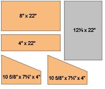 |
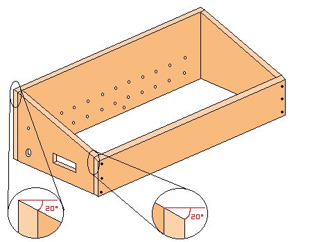
Start by cutting the ½"
plywood to the dimensions shown on the left. The tan pieces
represent the plywood, the gray piece piece is the ¼"
plywood/masonite (it will be used for the face of the board). The
front piece is 4" x 22", and the back piece is 8" x
22" (on both front and back pieces cut one of the 22" sides at
20º so it will be flush with the angled pieces - see diagram of assembled
box below). The angle between the 7¾" x 10 5/8" side
pieces should be 20º.
Plywood can usually be found at construction sites. Carpenters usually have PLENTY of scraps left over that would be perfect for this firing panel. |
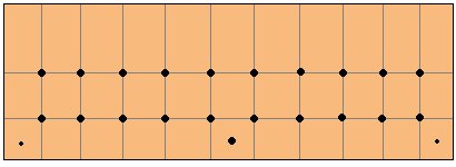
| On the back piece draw two horizontal lines at 2" and 4" from the bottom, and ten vertical lines at 2" intervals from the left to right. The lines should intersect at 20 places, as shown in the diagram to the right. Using a 5/32" drill bit, drill a hole through the wood at each of these marks. Also drill a hole 1" from the bottom of the box, between the 5th and 6th vertical lines. Using a 3/32" bit, drill two holes 1" from both the bottom and sides of the wood (as shown). Only drill about ¼"-½" into the wood in those two places. |
|
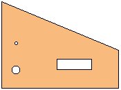 |
On the left side panel, drill a
½" hole at 2" from the bottom and 2" from the end.
This is where the power cord will come in to the box. On the same
side you'll also need to cut a hole to mount one of the switches on the
outside of the box (this will be the master switch).
OPTIONAL: if you want a power indicator light, drill a small hole, about 3/8" wide, above the power cord hole. |
| Assemble the box with the side pieces INSIDE the front and back pieces. Use three 1" wood screws or nails in each corner, as shown. |
|
|
|
On the face plate - the once piece
that isn't connected to anything - draw out a grid with the following
measurements: four horizontal lines at 3", 4", 8", and
9" from the bottom at 20 vertical lines at 1¾", 2¼",
3¾", 4¼", 5¾", 6¼", 7¾", 8¼",
9¾", 10¼", 11¾", 12¼",13¾", 14¼",
15¾", 16¼", 17¾", 18¼", 19¾", and
20¼". Cut out the small boxes (shown in white) formed by the
intersecting lines.
When this is done, take a switch, turn it upside down, and place it in one of the slots. Center the switch by lining up the flanges on the switch and the lines on the face plate. Use a pencil or pen to mark the two mounting holes, then drill the holes with a 3/32" bit. Do this for all 20 slots. |
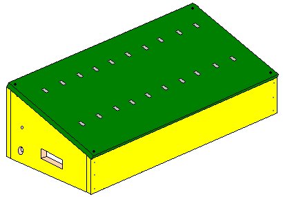
| Paint your box pretty colors. Start by painting the whole thing white, then paint it whatever color you want when it dries. You can paint the face a different color if you want. When it dries, screw the face plate to the rest of the box using the 1/2 wood screws. Try to stay ¼" away from the edges or the thing might crack. |
|
|
|
When the paint is dry, begin
inserting switches from the bottom on the box and attaching them into the
pre-drilled holes with mounting screws. Turn the switches
upside-down before you put them in. It will look like the switches
are in the on position, but they're really off. I do this because
it's easier to flip a switch down to turn it on than it is to flip it
up. Mount the last switch on the outside of the side of the box
where you drilled the hole. Attach the face plate to it, so it looks
like a regular switch you'd find on your house walls.
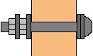
Take the # 8/32 bolts, add 2 washers, and insert them through the holes on the back panel (from the inside out). On the outside, and a washer, then a nut, then another washer followed by another nut. |
Before we wire the box, we need to get power into it. Take the 3 conductor extension cord and cut it in half. Take the half that is attached to the plug-in end with the prongs. Strip the outer casing about 8" to expose the 3 wires inside. Snip off the ground wire (colored green); you won't be needing it. Thread the remaining wires through the ½" hole you cut in the side of the box. Do this until the outer casing of the extension cord comes inside of the box. Once it does, use some high-strength adhesive to fill the hole area around the cord to secure it in place. Don't use hot glue; it won't work. For added strength, you could fasten the wires to the inside wall of the box using large hammer-in staples. Strip the end of the white wire and wrap it around the bolt (between the two washers) in the very middle of the back side of the box. Tighten the bolt. This will be the common ground wire. See the picture below for clarification. Strip and attach the black wire to one of the lugs of the master control switch (the one mounted on the side).
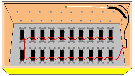
| Now we start wiring the box. Flip the box upside
down so the front end is still facing you (if you already haven't).
You should see something like the diagram on the right.
Take at the electrical switches from the underside of your box. Notice that it has both input/output lugs and two small quick connect sockets near each lug. A piece of stripped #12 gauge wire will fit snugly inside of the hole. Using red 12 gauge wire, connect the remaining lug of the master switch to the bottom quick-connect socket of the switch on the lower right hand corner. Wire that switch's lower lug to the quick connect socket of the switch right next to it. Continue this process until you've connected every switch on the board.
|
|
What you just created is an electrical bus where the switches act as circuit breakers. All 20 firing switches on the board are hooked up in a parallel sequence, that is, they will all receive electricity at the same time. The master switch on the side regulates the power that goes to the firing switches. If the master switch is off, then the circuit is broken and no electricity will reach any of the firing switches.
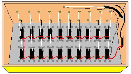 |
Run black wire from the remaining quick connect lug of the
top row of switches to the the corresponding bolt on the back panel.
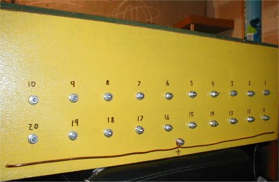
Do the same for the bottom row, but use white wire. Use a black
permanent marker to number the switches on the front panel and the
corresponding bolt on the back. The internal wiring of the box is
complete. Click
Here for an actual photograph of the wiring of my
box.
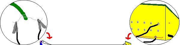
OPTIONAL: if you want, you can add a power indicator light that will turn on when you flip the master switch to let you know that the firing switches are getting power. You can buy small lamps down at a local Radio Shack. Put it in the small hole you drilled and glue it. When it's dry, attach one of the wires to the common ground bolt on the middle of the box's back panel. Attach the lamp's other wire to the bolt of the VERY FIRST switch you wired (not the master switch). Click on the link above to see a pic of my box. The lamp's wire is yellow. |
| Now make the common ground attachment wire on the back. Take a spare piece of 12 gauge wire and strip off all of the plastic. On the back of your box, remove the first nut and washer from the common ground bolt. Center the wire over the bolt and bend it around the bolt to form a loop. Put the washer and nut back on the bolt. The piece of copper wire should not come off of the bolt. Bend the ends (about 1") towards the box at a 90º angle, and stick them in the holes you drilled earlier. They should fit snugly, but if not, that's ok. Do not glue it. Click here for a more close up picture of the ground connection. |
|
To make the power supply, use the remaining half of the extension cord with the socket end. Strip the end where it's cut about 8" or so. Get rid of the ground wire. Attach the positive and negative wires to the large spring-loaded clips. When you want to connect the power, just attach the clips to the car battery posts. Use only a fully charged, high-amp car battery.
Now you're ready to start wiring your fireworks. Cut two lengths of 22 gauge wire however long the distance is between where the firing panel is and where the fireworks will be. It should be no less than 40 feet. If you're using firing wire, then just cut one piece (since there's two wires in each piece). Tape the wires together. It may be cheaper and easier just to buy multi-conductor wire of the same gauge. Multi-conductor wire is several insulated wires all bound together in one casing, like the extension cord. On one end of the wires, strip them and attach them to the eyelets. On the other ends, attach alligator clips.
CAUTION: Never wire fireworks while the box is attached to the battery!! Attach one of the eyelet wires to the number one switch by detaching the first nut and washer from the corresponding bolt. Put the eyelet over the bolt, and put the nut and washer back on. Take one end of the bare copper wire (the common ground) out of the little hole, slide the other eyelet wire over it, and push it back in. To fire a single device, you'll need some fine steel wire. Take a 4" piece of it and wrap it around the fireworks fuse two times. Clip the alligator clipped wire ends to each side of the wire. Hook up your box to the car battery. Turn on the main switch, and hit switch # 1 on the control box. Once the fuse lights, turn it off. Wa-la! Better than lighting the fuse and running away, huh?
Warning: Don't plug the box into a 120V wall outlet. Although it can plug in like an appliance, it's not very safe and it violates electrical code regulations.
APPROXIMATE COST OF PROJECT: Anywhere from $40 to $60, depending on whether or not you can get free wood and the cost of the supplies in your area.
Troubleshooting and Problems
*If the fuse doesn't light, you'll have to go back and check all of your wiring. Make sure that the bolt you've hooked the wire up to corresponds with the right switch you're flipping.
If you have any other questions, feel free to email me.
